Difference between revisions of "LaunchControl"
| Line 13: | Line 13: | ||
| − | |||
==Feature Wishlist== | ==Feature Wishlist== | ||
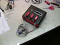
| + | [[Image:Minicontroldraufsicht.jpg|thumb|right|The rn-minicontrol board is simple, inexpensive, versatile, and perfect for this job]] | ||
* Launch controlled via Atmel microcontroller | * Launch controlled via Atmel microcontroller | ||
Revision as of 21:20, 12 October 2008

Model rocketry is a nifty hobby: You spend dozens of dollars on small rocket motors, light them via electrical "igniters" and hope that the parachute deploys. do {} while money > 0.
Alternatively you can save the money spent on "Estes"-brand igniters by getting yourself a 12V battery and just using some thin wire as electric igniter. But this also means the standard 9V-powered launch controller does no longer cut it.
Since commercial model rocket launch systems are little more than glorified electrical switches with fancy stickers and a shocking price tag (like for example the Aerotech Interlock Controller at http://www3.towerhobbies.com/cgi-bin/wti0001p?&I=LXRTG9&P=M which retails for over 40 dollars!) I decided to make my own launch system. A model rocket launch controller is essentially just a switch (or button). For added safety we're mostly talking about two buttons that have to be pressed at the same time, and very often there's also a key that has to be turned before you can launch your missile. All these things do in the end is send 12V down a cable to a thin wire or a disposable pyrotechnical igniter, yet they try hard to look intimidating and make you feel like you're about to launch the next Moon mission. That's part of the fun, so why not go a little overboard and make something that turns an otherwise dull flick of a switch into a little event of its own?
Feature Wishlist

- Launch controlled via Atmel microcontroller
- Three-stage safety switch sequence
- LED-lit safety switches
- LED-lit launch button
- Minimum ignition length timer
- 60 second Post-launch timer (=wait time after a misfire)
- Relais-switched ignition circuit
- Main switch overriding any launch command by removing all power
- 2x16 character display (super-bright, backlit, daytime-readable)
- 12V rechargeable Lead Gel battery
- Self-contained in a single case
- 10m launch cable with sturdy XLR connectors
Operation procedure
Three safety-switches have to be activated in-sequence. The first switch powers the microcontroller, while the second and third have to be set one after another to progress through the sequence. Any non-sequential switch action will lead to the system to go into a DISARMED state. Once a sequence is complete and valid, the launch button will become active. Pressing the launch button will activate the relais for a minimum of 2 seconds. A post-launch count-up will start after pressing the launch button, telling when it is safe to approach the missile after a misfire. After ignition the system goes into the DISARMED state. The entire sequence has to be repeated for every launch.
Using the first stage switch as a power switch is rather convenient since we don't need another power switch, we save one port on the chip (two if you want to drive the switch LED via software) and you don't run the risk of accidentally leaving the thing on.
Software
The software was written in AVR Basic, because this hides many of the complexities of AVR programming behind ready-to-use function calls. For example, programming the display is a matter of a few lines of code. Since the software launch command can be overridden with the switches, the software is not extremely safety-critical. There are a few special considerations to be kept in mind: For example, the system should not "skip" steps in the switch sequence, and it should also detect whether it was powered on with one or more of the next switches in the sequence a lready set to enable. Last but not least, every step in the launch sequence is accompanied with dramatic text and animations on the display. If your controller has enough free ports, you can even drive the LEDs of the switches and the pushbutton via software for extra effect.
If you're interested (and if it helps you at all) the software is available on request.
Hardware
I chose the "RN-minicontrol" board from robotikhardware.de, which is a ready-to-use microcontroller board with lots of useful features like built-in voltage control, serial port, standardized terminals, etc. The RN-minicontrol board comes built and tested, but of course any self-built atmel-powered board will do. You need enough ports to drive a 4-bit LCD bus, as well as four extra ports: Safety switch 2, safety switch 3, launch button, and the relais output.

Since a microcontroller has a hard time directly driving a relay, a simple transistor circuit takes care of that.

I chose XLR for the connector because it's a sturdy connector with a self-retaining mechanical lock. Actually you can purchase a 10m XLR audio cable and use that as launch cable.
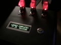
For the display, I was able to snatch a now-discontinued PLED 2x16 character module. PLED displays are similar to OLED, but much brighter and with even higher contrast. In fact, I have never seen such an amazing display - it's vastly superior to standard LCDs and extremely well suited for this project. The color is a piercing bright yellow, it's viewable from ANY angle and thus a perfect match for a missile launch system. If you can't get a PLED display (and you won't!) then a regular backlit LCD will have to do. Connection and programming are the same anyway.
For the switches I chose a model in the style of nuclear devices in old movies, i.e. with a safety cap. For extra effect these switches also contain a LED at the tip. The switches are of the closing type, i.e. they connect a port on the microcontroller to GND when enabled.
The launch button is a massive "vandalism-proof" model with a LED-ring. Really, any button will do, but this is about being cool, not reasonable ;) This button is also a closing type, connecting a controller port to GND when pressed, and breaking the contact when released again.
The entire thing is housed in a single KG22-case, and powered by a 12V lead battery. Extra terminals allow for easy recharging without opening the case.
Assembly
I started with a KG44-ish case, and released any pent-up frustration from work on it. This usually results in a couple holes that can be used to mount buttons and whatnot. The display can be mounted using hot glue, but you're welcome to go for something more sophisticated. I don't screw around.
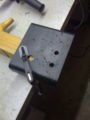
Drilling the case holes
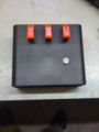
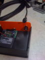
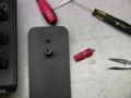
Test-fitting the switches

Yep, looks fine

Display mounting
A bit hot glue will do fine for this
XLR connector


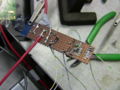
Since I don't have a lot of parts I chose to hot-wire some of the circuitry. Regardless whether you prefer to do pull-up or pull-down resistors, it's quite simple to solder them directly onto the switch and just have wires go directly to your microcontroller board.
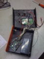
Controller module, battery, and XLR cable+connector
Soldering GND to switches, +12V goes to Switch 1 on the right
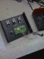
Switches and button connected to processor board

Black is GND, each switch has a 10k resistor (hidden by tape) going to GND
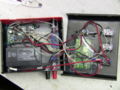
Put some isolation on the display. The switch in the front is the master switch which can remove power from the entire device
Ready for programming!


Now it's time to write some code. Reading the state of the switches and button is a trivial exercise which depends on your choice of microcontroller. Note that there's no output yet - we don't really launch anything yet. But it's the perfect time to play around with the display animations and get the basic program flow done. You can already define some of the unused ports as outputs and toggle them in your program, but we'll have to build a little driving circuit to be able to really do something.

The switch LEDs are not driven by the controller, they just light up when the switch is on
Any serious microcontroller project must count seconds somewhere...


Ok, now we have all the fancy effects and we can flick switches on and off like this were a nuclear missile control panel - but ultimately nothing happens. Yet. In order for the chip to be able to work a relais contact or a LED, you should definitely build a transistor driving circuit. NEVER hook up a relay directly to a microcontroller.
This little circuit below is basically all you need to drive a relay. The other end of the 10k resistor goes to any free output pin of your controller. The transistor switches the relay coil for us, which draws more current than the microcontroller can handle. But since this is a transistor, a small current is enough to switch it on and have that little guy take the load for us. The 10k resistor limits the current used for switching the transistor. The diode gets rid of some pesky coil-related things for us. Basically when you switch off the relay coil, there's a voltage spike. The diode relieves us of that worry.
If you want to drive a LED, just put the LED instead of the relay/diode combo. Note the LED polarity should be opposite to that of the relay-diode (i.e. arrow pointing downwards in this diagram), otherwise it won't light up.
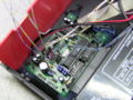
The exact circuit will depend on what you want to do. I only have one LED to switch, and of course the ignition contact. This means two transistors, two 10k resistors, one diode and one relay. I built this circuit on a little board and then hot-glued it into the case. Make sure you wire the + of your circuit to the +5V coming from the microcontroller, NOT the battery's 12V terminal!

Circuit for driving a relais

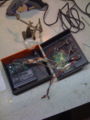
The ingredients for the ignition output switching

One BC548 drives the relais, the other drives the launch button LED
Backside. Note the use of all relais contacts in parallel
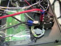
Connecting LED and ignition contacts to the board

Exercise for the reader: Do this in a less messy way...

Hot glue to the rescue

Almost done


Now before closing the case for good, it might be a bright idea to add a means to recharge the battery without having to whip out a screwdriver again. Some leftover banana terminals or any other connector is good, really. I chose the bananas because this allows me to also use the built-in battery as an emergency power supply on the flying field.
Recharge terminals
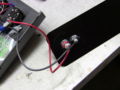
Make sure recharge terminals are directly connected to the battery
All done!


Alright, time to close the case on this one, literally.

Test
Here's a short video of LaunchControl courtesy Youtube:
<embed src="http://www.youtube.com/v/w8lEuGlq2-0" type="application/x-shockwave-flash" width="425" height="350"> </embed>